I’ve been a developer for a long time. I can code almost anything. I have a great desire to take my understanding to the next level. I am a C# coder, which is managed code, my objective is to not move to a native language like C or C++, instead I want to take it to the zeros and ones. I recognize the existence of compilers which are the logic that translates my code from the if, then, else, switch, where, for, etc.… words into binary which a computer can then use to execute my instructions. I am looking towards assembly and I want to see the bits (0 and 1) traverse the CPU. My understanding of the early days of the computer, perhaps the earliest day had to do with a light bulb which can be off or on, where 0 = off and 1 = on, which are bits and trigger thoughts of Booleans when I see that. With two light bulbs you can have four values, 00, 01, 10, 11 (aka off/off, off/on, on/off and on/on). With four lightbulbs you get 24 values which is 16 and commonly referred to as a nibble (0000 – 1111). Then finally, 28 which is 256 values, which is a byte (00000000 – 11111111) and is where the 6502 processor comes into the project, it is one of the first 8-bit processors, 8 bits = 1 byte. It is was in the first computers I coded with which was an Atari 1200XL. One of my learning objectives is to try and visually find a link between my lightbulb analogy, I.e. 0’s and 1’s and and a single CPU cycle of a byte through it.
Here is where I plan on ending up which is the writing of ‘Hello, world’ to an LCD. Before I begin my journey, I must admit that this area isn’t something which I have studied or have any formal training on, it is simply something of interest to me. I like electricity, breadboards, integrated circuits, resistors, capacitors, ICs (555, 74LS04, 74LS08 and 74LS32), oscillators, potentiometer, etc. As I watched those series of video’s I did see some familiar patterns when it came to memory addresses, assembly commands, binary outputs, which I see when I am analyzing memory dumps. Here is my favorite memory dump post of mine. I think, I hope I am jumping into the deep, hopefully too deep to be applied, but I hope to bridge the gap from this breadboard project to some code. I expect it to be helpful in my understanding. As I read in the the book “The Joy of X – a guided tour of math, from one to infinity” – “battling obstacles give rise to great beauty.”
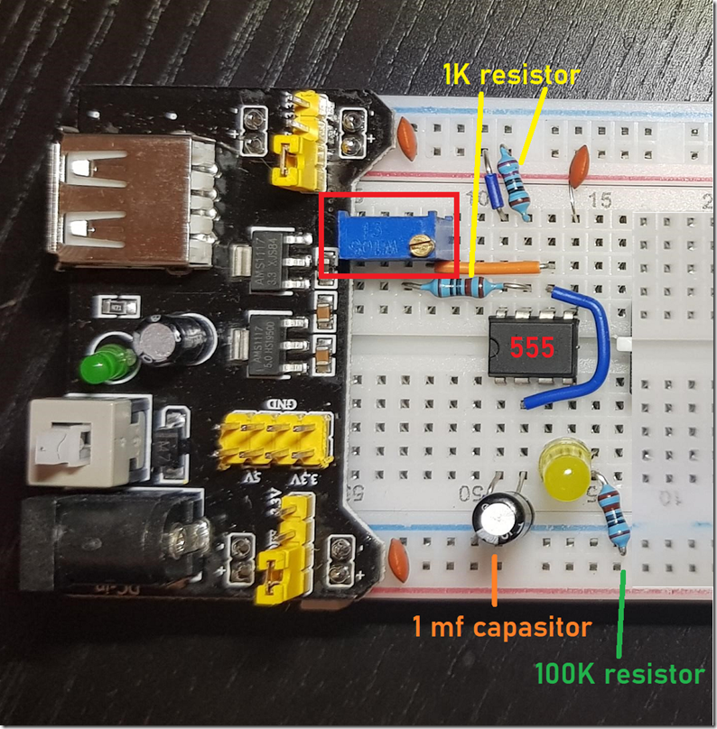
It all starts with the creation of a system clock which outputs an oscillating clock pulse. This clock is used to coordinate digital circuit actions. The (1 mega-ohm) potentiometer (variable resistor) which I have placed on the Astable 555 timer segment is used to increase or decrease the clock rate, Figure 1. The rate which is set is the value used to determine the speed of the CPU. These days the speeds are usually at the Gigahertz per second, but the one you see in Figure 1 is set to cycle once per second, but can be increased to about 1,000 per second. You can choose different sizes of potentiometers which support higher frequencies.
Figure 1, Astable 555 clock module
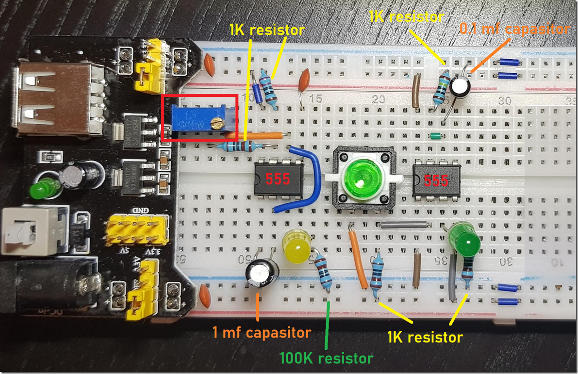
In the Monostable 555 timer segment of my computer clock, Figure 2, I can manually cycle the clock one step at a time, by pressing the button. This allows me to step line by line through the processes flowing through the CPU. The addition of the 555 integrated circuit is to “”debounce” the button. When the button is pressed it is possible that the mechanics of it results in more than one click. The 555 resolves that issue because if you need to step one cycle at a time, you don’t want it to make two steps just when you are about to find that bug!
Figure 2, Monostable 555 clock module
A few notes I need to mention about what I have learned up to now.
- All these pieces like capacitors, switches, buttons, resistors, etc. do no come in small quantities. Expect to purchase 50+ even if you need only 1.
- 2 of the 5 – 555 Time circuits have been defective, during my troubleshooting, when the configuration didn’t work, switching them out resolved the issue.
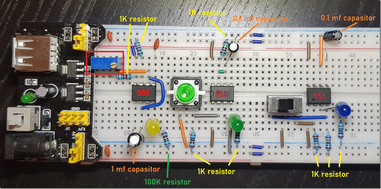
- The breadboards I got seem to not send power past pin 30. I do not know why. This was found when I was working on the Bistable 555 module, Figure 3 and it wouldn’t work. That took a lot of troubleshooting to discover, and is why you se the blue wires connecting pin 30 with pin 31 on the breadboard in both Figure 2 and Figure 3.
- You should have at least 2 of each required part and assemble it stand alone on the first, then add it to the final one, this is helpful with troubleshooting why it is not working as expected
I am not yet 100% sure of the purpose of the Bistable 555 module, other than making it easy to switch between Astable and Monostable modules. I assume I will hook the 6502 into this timer module once it gets ready.
Figure 3, Bistable 555 clock module
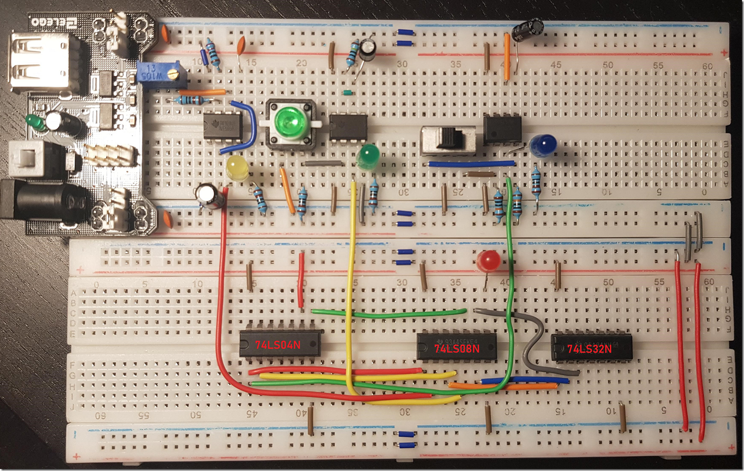
The last step is to combine the Astable, Monostable and Bistable signals into single output signal for the clock circuit. The Bistable module will control which signal is sent to the clock circuit, either the Astable osculating signal or the Monostable manual signal. Mission complete as seen in Figure 4.
Figure 4, Completed Astable, Monostable and Bistable 555 clock module
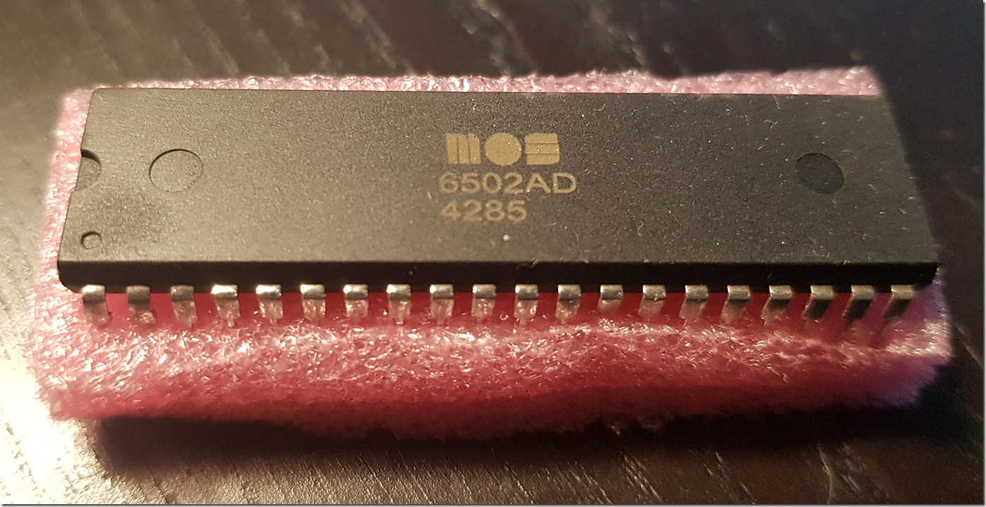
I set this module up on the first try, but I used jumper wires and not the ones shown in the picture because they are easier to add and remove. I was very careful and replaced those jumper cables with the ones shown and guess what, it didn’t work anymore after I completed the modification. I did it over and over again at least 5 times placing the wires and chips in exactly the correct place, checked the power flow a few times, nothing. I assumed that, like I experienced with the 555 timer circuit that either the 74LS04N, 74LS08N or 74LS32N has short circuited. When I originally got those chips, I only got one of each, in addition to many other 74LS**N chips which I have yet to need, so I have to order more. I replaced the 74LS08N chip first and there was no change so it wasn’t that one. Then I replaced the 74LS32N it did some flickering, turns out I put it in backwards and seems like it blew out my power supply. Once I replaced the power supply, thankfully I had a few backups and put the 74LS32N in the correct direction, bingo, it started working as expected. Now I can begin doing the 8-bit programming using the 6502 chip, Figure 5, and get to learning.
Figure 5, 6502 8-bit computer chip
